Lunar Reconnaissance Orbiter Camera Narrow Angle Camera: Targeting Background Materials
Introduction
The LROC Science and Operations Teams have prepared the following set of materials to familiarize outside members of the lunar science community with the LROC targeting strategy, the operational constraints on LROC NAC observations, and the current status and distribution of LROC NAC Targets. The LROC Science Team is expeditiously entering targets to prepare for forthcoming LRO on-orbit operations at a rapid pace, so the materials on this website should be considered a "snapshot" and will be updated on a semi-regular basis prior to this meeting.
Click here to download a Final Report of this meeting (PDF).
LROC Targeting Update Presentation
This overview presentation summarizing LROC NAC Targeting was originally presented on 3 December 2009 by Mark Robinson, Samuel Lawrence, and Brad Jolliff to representatives from Constellation Program, the NASA Lunar Mapping and Modeling Program, NASA HQ, MSFC, JPL, LPRP, GSFC, JHU-APL, and JSC. It has been updated for presentation on this website, and is current as of 20 January 2009.
LROC NAC Targeting Strategy
LPSC XL abstract summarizing the LROC Science Team's NAC targeting strategy and target sources (Brad Jolliff, Washington University in St. Louis).
LROC NAC Targeting Constraints
LPSC XL abstract reviewing projected constraints and capabilities of the LROC NAC imaging subsystem during the LRO's Exploration mission (i.e., the 50-km nominal mapping orbit; Samuel Lawrence, Arizona State University).
Constellation Program Targeting Information
The following fifty sites have been provided by Constellation Program (CxP) to the LROC Science team for entry as Priority 1 LROC NAC targets. These targets are provided in alphabetical order, with no priority implied by the order.
Download 'Cx LROC Tier1 FINAL.pdf' (Adobe PDF)
Download 'Cx LROC Tier2 FINAL.pdf' (Adobe PDF)
Note: The above PDF files are the final versions.
LROC NAC Regions of Interest
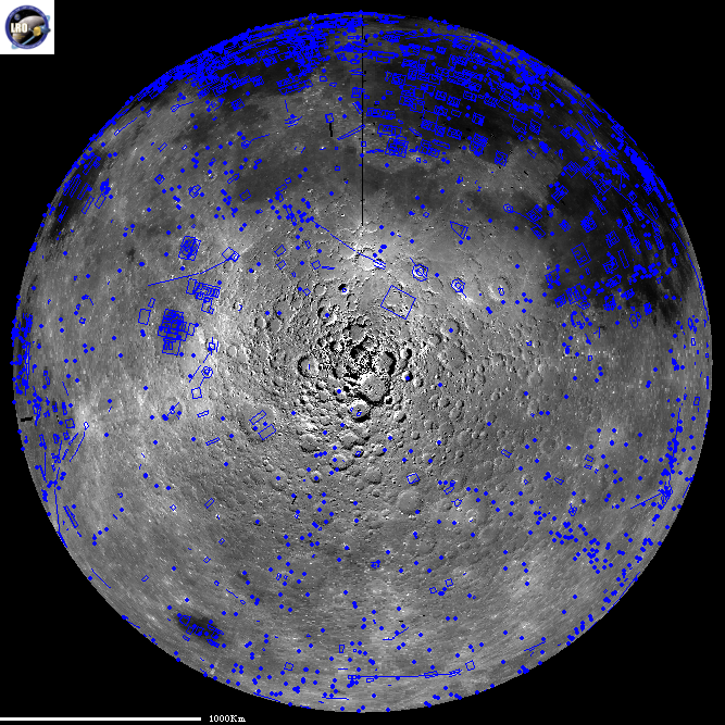
These figures show the distribution of all targets in the LROC NAC Master Targeting Database as of 14 May 2009.
Targeting in the lunar polar regions is on hold pending release of the improved Kaguya topographic dataset.
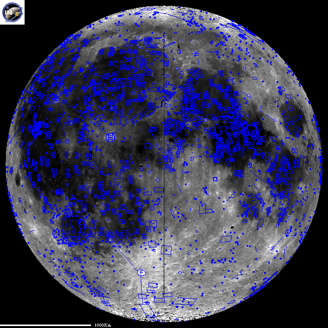 Nearside |
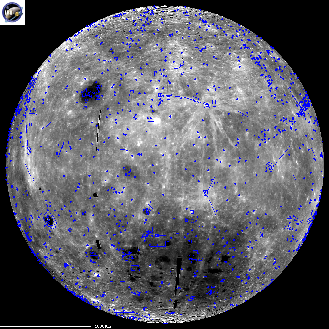 Farside |
 North Pole |
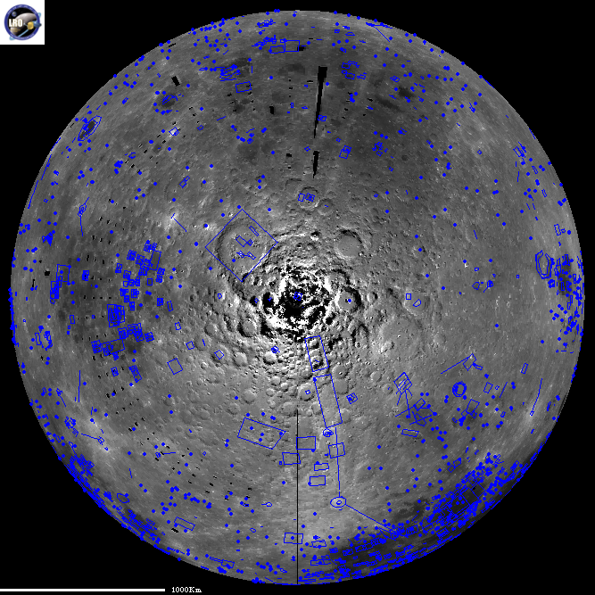 South Pole |
Current targets available in spreadsheet format (as of 14 May 2009).
Download (Microsoft Excel 2003 Binary Format)
Lunar Reconnaissance Orbiter Mini-RF Technology Demonstration: Targeting Background Materials
Targeting Strategy
The Mini-MF instrument on LRO is in a unique position in that it will be operated in concert with a companion instrument currently operating onboard the Indian Chandrayaan-1 spacecraft. Exact details of the targeting strategy for the Mini-RF on LRO will be largely dependent upon the radar data collected by the radar on Chandrayaan-1.
The overarching science goal of both instruments is the same: to search for the presence of ice in permanently shadowed regions at the lunar poles. To this end, the goal of Mini-RF on Chandrayaan-1 is to collect data over both polar regions at latitudes poleward of 80° N and S. The radar on LRO will target specific areas identified by Mini-SAR of Chandrayaan-1 as potentially ice rich for more detailed analysis, and will also to help fill in any gaps in the polar radar coverage.
LPSC XXXIX abstract summarizing the Mini-RF instrument capabilities targeting strategy (Ben Bussey et al., JHU Applied Physics Lab). Download (Adobe PDF)
Targeting Constraints
Mini-RF on LRO will operated in both S band (like Chandrayaan-1) and also X-band. The baseline resolution is ~75 meters, and there is also a zoom mode with a resolution of ~15 meters (at LRO's nominal 50 km altitude).
On LRO, current operations plan calls for one four-minute SAR (synthetic aperture radar) data collection per month, plus an additional set of four two-minute data collection periods (on four consecutive orbits) twice a year. Additional opportunities to collect data are desirable, particularly since if Mini-RF collects a strip of data exactly every 28 days as planned, the data coverage will be restricted to a limited geographic region of the lunar surface.
On Chandrayaan-1, Mini-RF is limited to data collection periods on the non-sunlit hemisphere (for thermal constraints) and periods of high phase angle conditions (which are non-optimal for optical instruments).
Regions of Interest
These figures show an example north and south polar radar orbit during the nominal mapping campaign of Chandrayaan-1. Mini-RF on LRO will principally be targeting regions of further interest and/or gaps within the Chandrayaan-1 coverage.
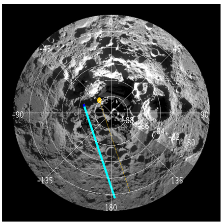
Figure 1. South polar Clementine mosaic from 78-80° S lat. Thin yellow line is projected spacecraft ground track (yellow dot indicates start of pass); blue line indicated radar swath. Look direction is right-looking in this example.
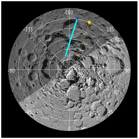
Figure 2. North polar Clementine mosaic from 78-80° S lat. Thin yellow line is projected spacecraft ground track (yellow dot indicates start of pass); blue line indicated radar swath. Look direction is right-looking in this example.
Diviner Lunar Radiometer: Targeting Background Materials
Targeting Strategy
Diviner will primarily be operated as a nadir staring, pushbroom mapping radiometer. However, due to its Mars Climate Sounder (MCS) heritage, Diviner is uniquely capable of targeting independent of the LRO spacecraft. Diviner has azimuth and elevation actuators, each with 270 ° ranges of motion. Diviner has nine spectral channels to measure reflected solar and emitted infrared radiation between 0.3 and 400 microns.
Diviner's science goals are as follows: (1) to map surface temperatures and investigate the daytime, nighttime, and polar thermal environments, (2) to map surface properties (e.g. thermal inertia, surface roughness, albedo, silicate composition), and (3) to identify permanently shadowed regions and characterize thermal conditions related to volatile stability.
The following LPSC XL abstract contains additional information about the Diviner instrument and observations: http://www.lpi.usra.edu/meetings/lpsc2009/pdf/2255.pdf
Targeting Constraints
In order to generate a more complete and consistent dataset, Diviner will be operated in a nadir staring orientation for much of the 1 year mapping phase. Interruptions to continuous nadir staring include 10 in-flight calibrations per orbit and LROC and Mini-RF off nadir targeting operations. Diviner will collect "ride-along" data for most LRO targeting operations.
Diviner is capable of independent targeting, which will be tested during the commissioning phase for occasional use during the mapping phase, and potentially more extensive use during any extended mission phases. Diviner has two principal off nadir modes: (1) cross track pushbroom and (2) in track "comb". In the cross track pushbroom mode, Diviner looks in the LRO ± y direction and maps parallel to the LRO orbit track which is at a different lunar local time. For the in track "comb" mode, Diviner looks in the LRO ± x direction (analogous to MCS limb sounding) and views targets with variable phase angle within the LRO orbit track. However, in this mode, Diviner's detector arrays are perpendicular to the lunar surface and Diviner must raster in azimuth to create images. Diviner is also capable of imaging non-lunar targets of interest, including parts of the LRO spacecraft and the Earth.